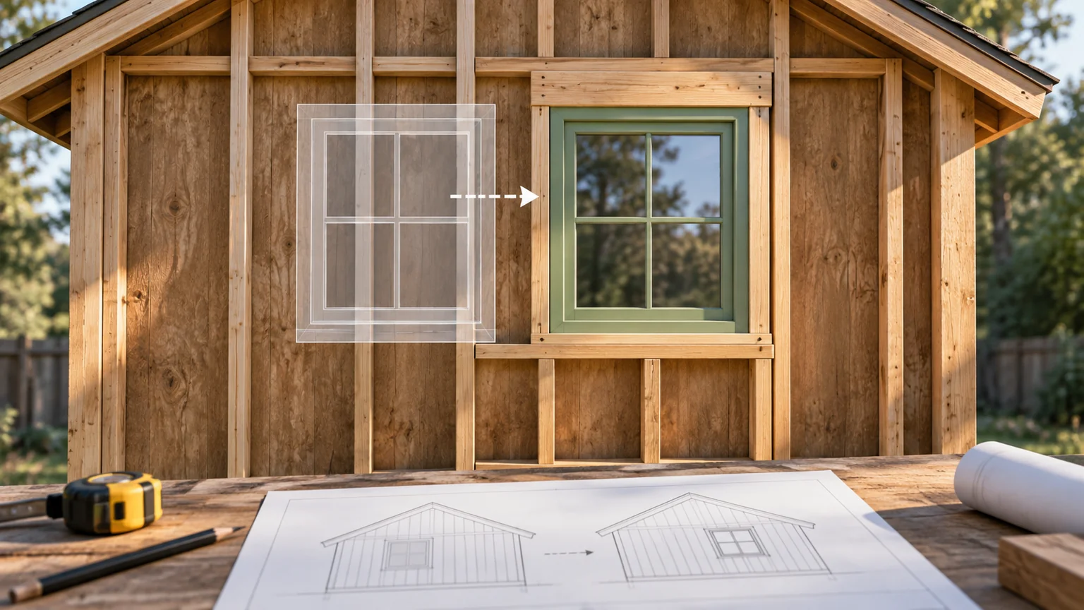
You want to move a window a little to the right. Perhaps a tall cupboard needs that wall, or the desk would work better with daylight beside it. On the screen, the change takes a moment.
Before you say “that looks good,” ask what else changed with it. The opening, its surrounding framing, the drawing and the materials list all need to describe the same decision. If only the picture changes, someone further down the line may still be working from the old plan.
This guide shows what to look for without needing to understand the software behind it. We will move one window in a small shed, compare the results, and try a move that puts it too close to the corner. Open the interactive example when you want to try it yourself.
Start with the reason for the move
Tell your designer what you are trying to make room for. “I need this cupboard beside the desk” explains more than “move the window one foot.” Include the cupboard’s actual size and anything it needs to open or connect to.
Ask which dimensions will stay fixed. A horizontal move may leave the window’s width and height alone, but a different product or sill level would introduce more decisions. Keeping the request specific makes the result easier to check.
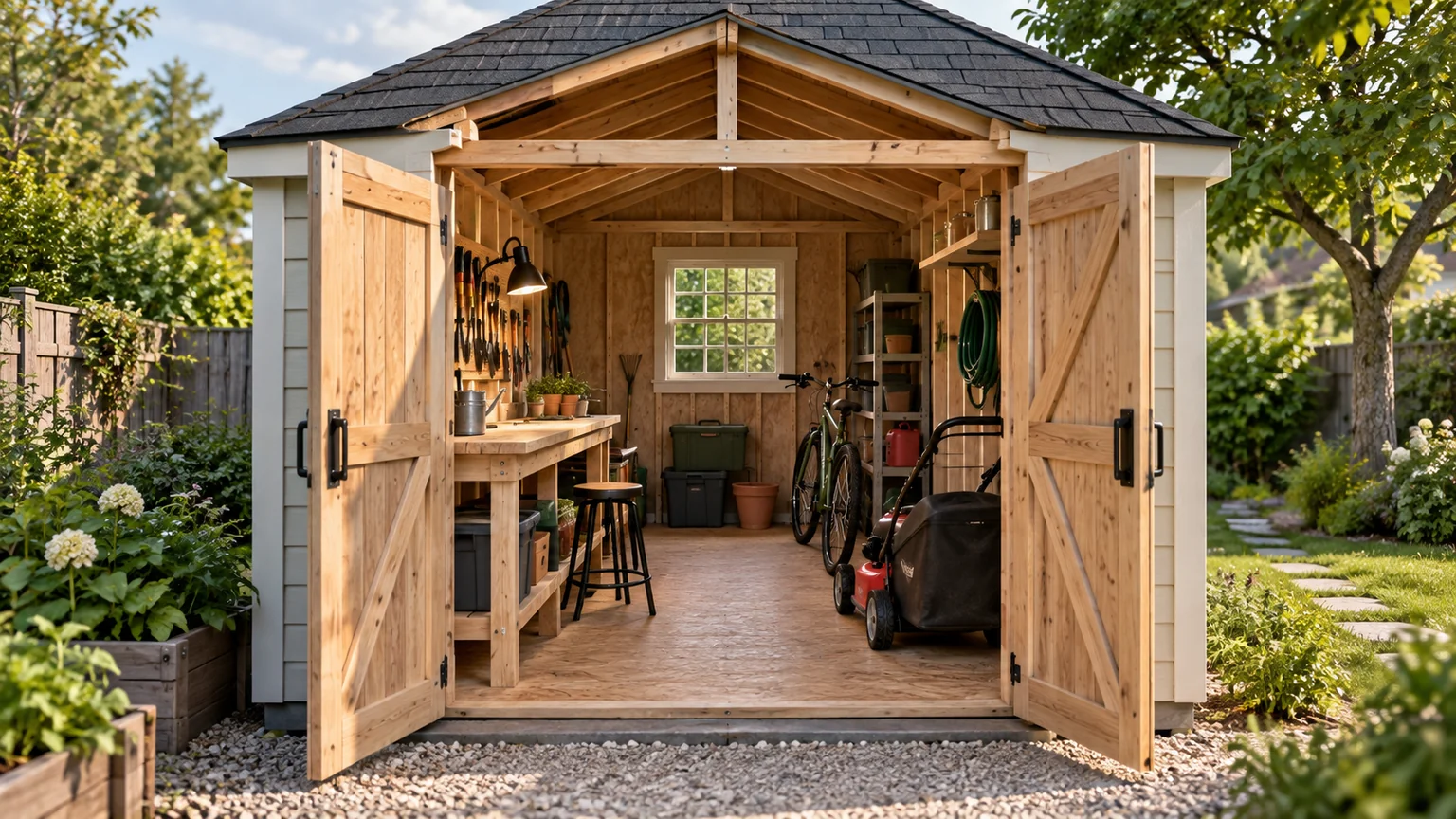
Our example uses W01, the rear window opening in the 10 × 12 shed guide. W01 is just a label so everyone can identify the same opening in a model, drawing or list. It is 36 × 36 inches, with the bottom of the opening 43½ inches above the finished floor—the surface you stand on.
These are modeled opening dimensions. A selected window product and its required rough opening still need to be coordinated with the manufacturer’s instructions.
Compare the old and new position
Choose 12 in right in the example. The window moves one foot across the rear wall, while its size and height stay the same.
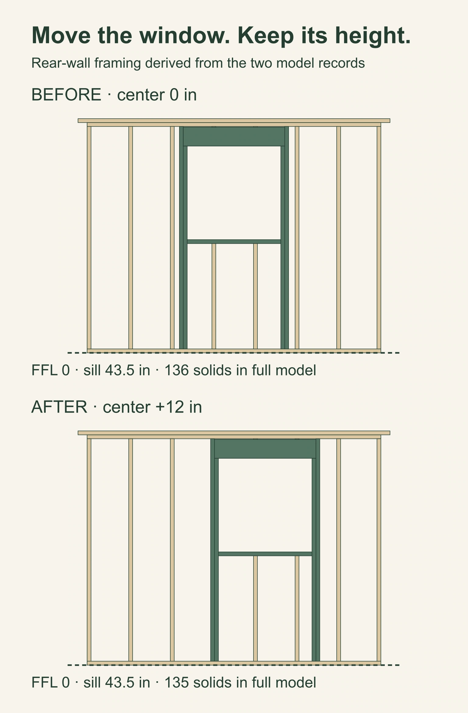
The table uses the center of the wall as zero. A minus sign means left of that point; a plus sign means right. This makes the position easy to compare in the exported drawing and record.
| Measurement | Before | After moving right |
|---|---|---|
| Window center | 0 in | +12 in |
| Left opening edge | −18 in | −6 in |
| Right opening edge | +18 in | +30 in |
| Bottom of opening above finished floor | 43½ in | 43½ in |
| Top of opening above finished floor | 79½ in | 79½ in |
Look at the wall straight on as well as in 3D. The door, floor and roof should remain as they were in this example. An unexpected change elsewhere deserves an explanation before you accept the revision.
Look around the window, too
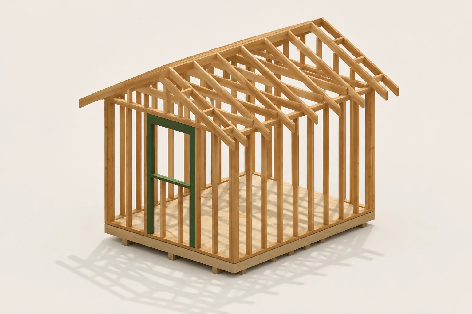
The green selection in the viewer highlights the framing around W01. It includes the full-height king studs, the jack studs supporting the header above the opening, and the sill below it. Moving the glass alone would leave these parts behind.
Here the framing is generated from the accepted opening position. Moving W01 changes which stud positions it crosses, so the whole model’s count changes from 136 to 135 identified geometric parts.
That result is specific to this model and this move. Moving a real window does not necessarily save a stud or reduce a price. The useful lesson is that the quantity output has changed with the wall, and you can trace the change to the same revision.
Ask your designer what the move means for the actual structure, product, weatherproofing and services. The example checks whether the modeled parts stay coordinated. It does not determine which header or connection is suitable for your building.
See what happens when there is not enough room
Choose Try corner conflict. The example proposes moving the window center 48 inches to the right of the wall center. That puts the opening and its surrounding framing beyond the boundary this model allows near the corner.
The proposal is rejected, with an explanation. The last accepted model remains in place, so you can return to it without trying to reconstruct what you had.
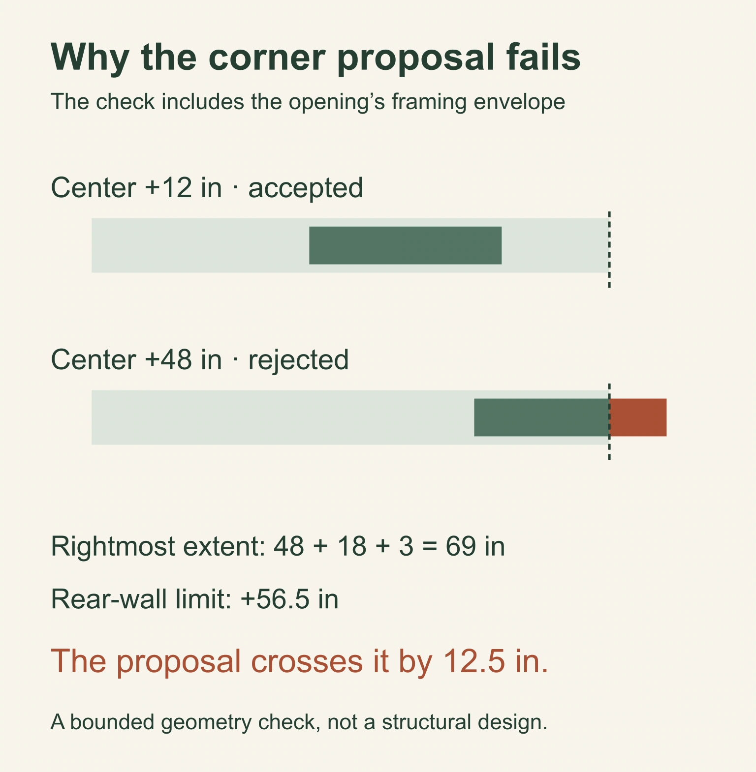
You do not need the boundary arithmetic to use the lesson: a design tool should explain when your request does not fit. Silently shrinking the opening or moving another wall would change the brief. If a compromise is needed, you should be able to understand and choose it.
This demonstration checks one opening against one corner condition. It has not checked every neighboring opening, service or structural arrangement a real building could contain. Ask what the tool supports before treating a successful edit as a complete review.
Keep the height tied to the right floor
A horizontal move leaves the bottom of W01 at 43½ inches above finished floor. In this model, finished floor is the zero reference level.
That sounds simple, but “window height” can mean several things: the size of the product, the height of its top, or the height of its bottom above a chosen surface. Write the meaning beside the number.
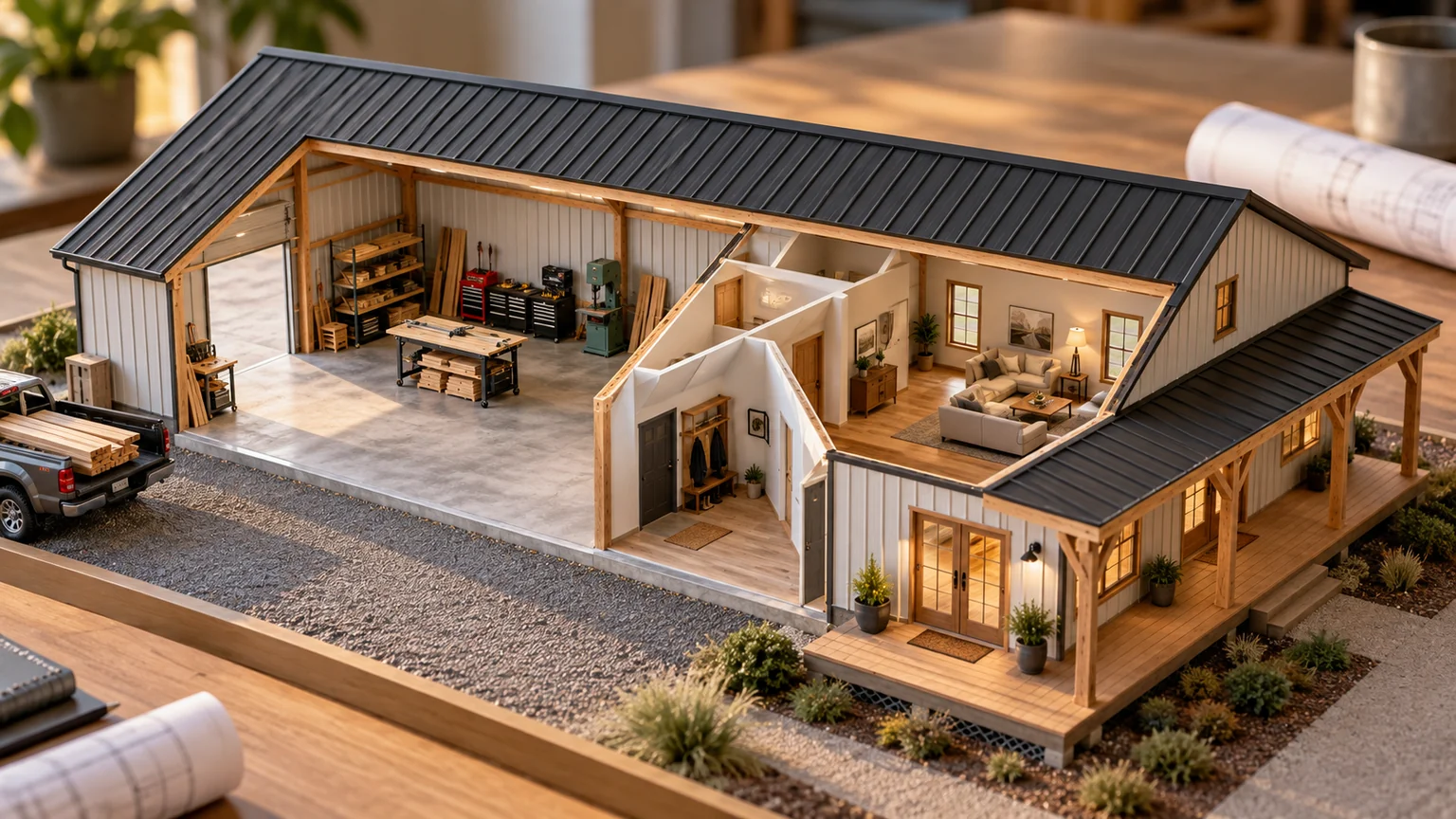
Use the same habit for outdoor spaces. A porch needs a clear floor level and boundary so it is not accidentally treated as an enclosed room. In the barndominium planning guide, the proposed porch stays outside the enclosed area total, and its access details remain a separate design question.
Open the files someone else will receive
Once you accept the window move, choose Download drawing. It produces an SVG drawing containing the plan and rear elevation for the current revision. Download record saves a JSON text record containing the dimensions, position, wall identity and model inventory.
For this rightward move, the revision is BL-W01-R12. Compare that label, the +12-inch center position, the 43½-inch sill height and the 135-part count wherever those values appear. Save the original too if you want a before-and-after comparison; reloading the page resets the example.
For a real project, agree the file formats with the people receiving the design. If they use IFC, an open standard for exchanging building information, check a sample export in their tools. A correct authoring screen does not prove that every required object or relationship survived the exchange. Our browser example exports JSON and SVG, not IFC. buildingSMART’s introduction to IFC.
A small checklist before you approve the change
You can use these questions for a window, door or another change to a plan:
- Does the revised position solve the everyday problem that prompted the change?
- Are the surrounding parts, drawings and quantities updated with it?
- Have the dimensions that should stay fixed actually stayed fixed?
- Are conflicts explained, with the previous accepted version recoverable?
- Do the files being handed over show the right revision?
You are looking for a change you can follow from the original request to the final drawing. That makes it easier to have a useful conversation about the price, the remaining design work and the next decision. The companion guide explains five checks before trusting a 3D house plan.
Keep a good idea close.
Follow Blueprint Lab