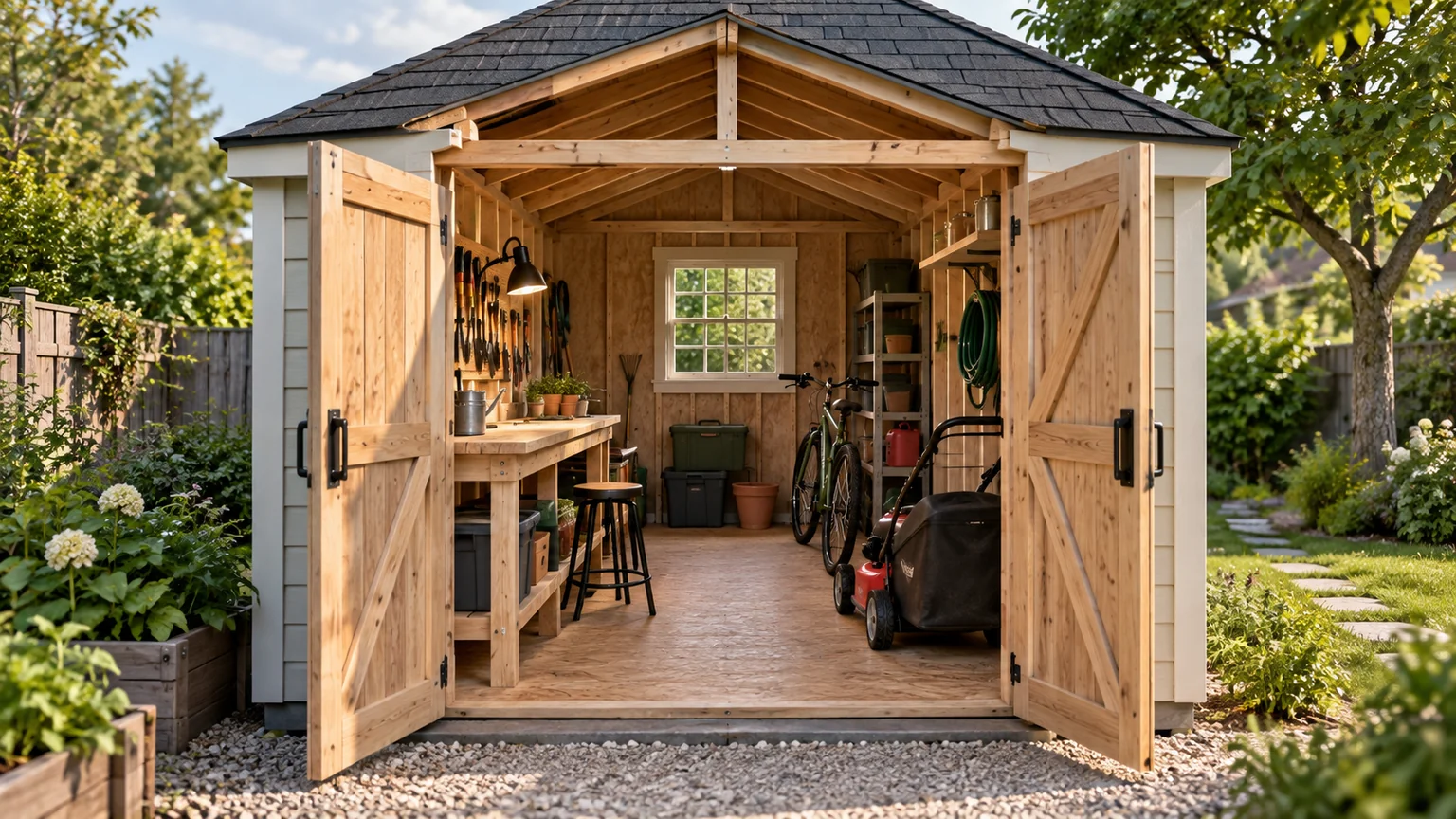
Picture the first wet afternoon with your new shed. The mower goes in, the doors close, and everything looks fine. Then you need the bicycle behind it. Now the mower has to come out again.
A shed can hold everything and still be frustrating to use. Before choosing the cladding or roof color, work out the space inside the walls, how you will get things through the door, and whether you can reach what you need without emptying the building.
Is a 10 × 12 shed big enough? It depends on your things and how you use them. The measured example below has about 107½ square feet between its exposed inside framing faces. Start with that usable rectangle and your largest object, rather than treating the 120-square-foot outside footprint as empty storage space.
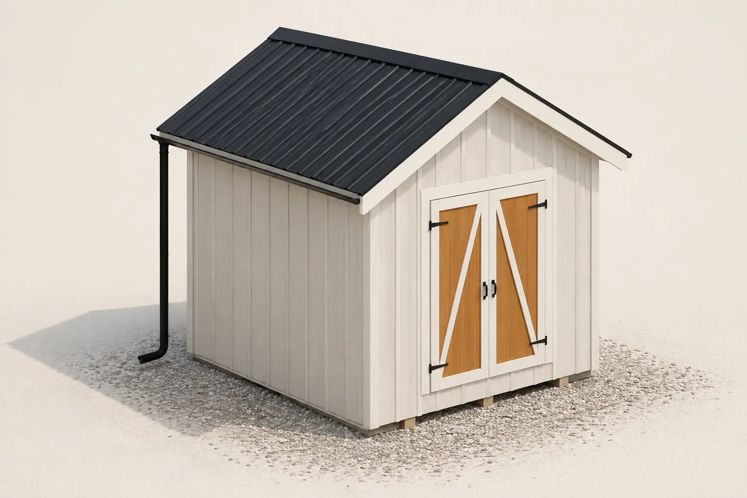
We will use a measured 10 × 12-foot example from Blueprint Lab’s shed-design work. You can open its model at any point. The numbers below describe this particular planning model; they are a useful starting point for a brief, rather than a ready-to-build specification.
Start with the space between the walls
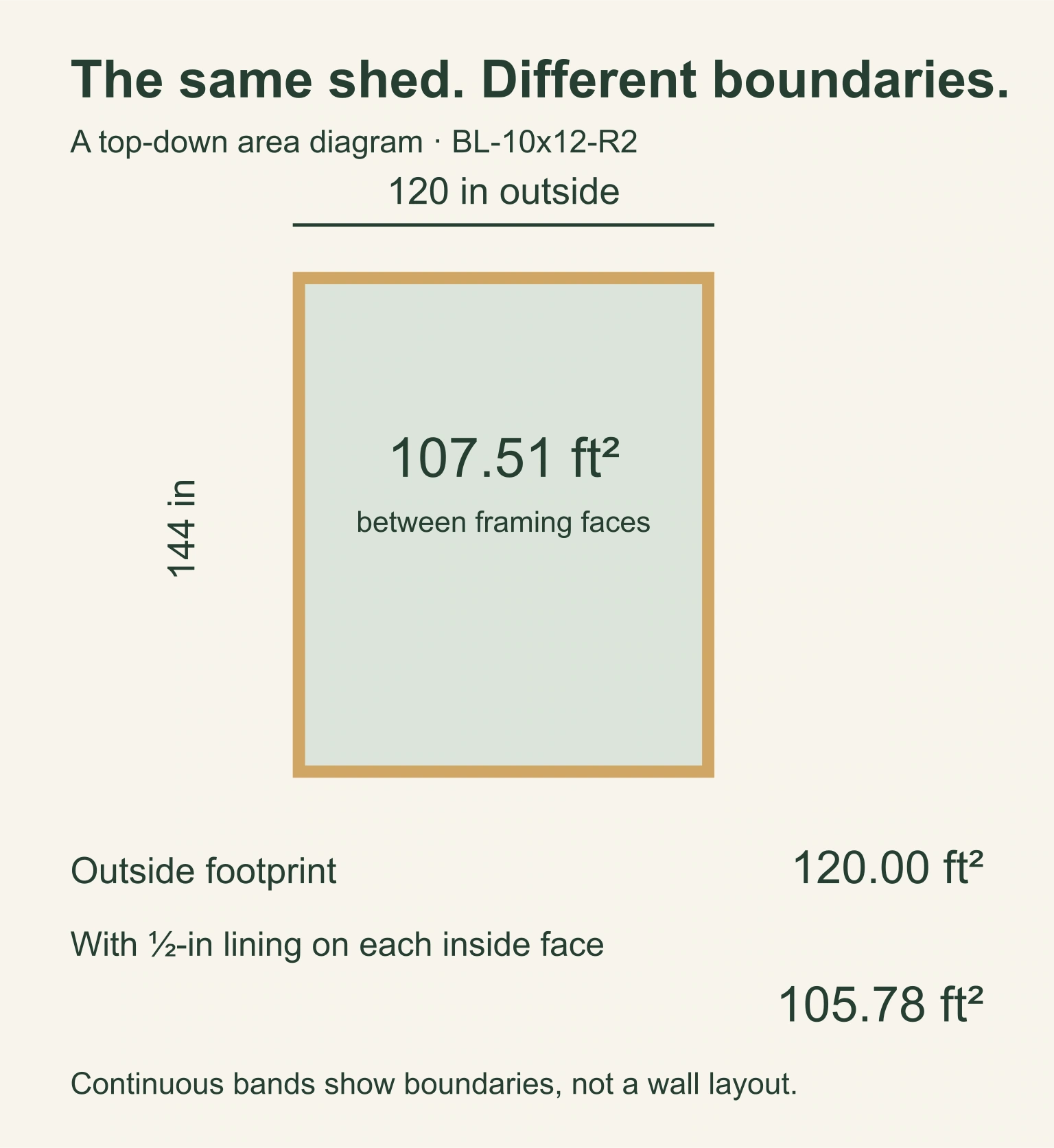
“10 × 12” tells you very little until you know where the measurement starts and stops. In this example it means the outside faces of the wall framing. Siding sits beyond that line. The inside faces sit within it.
The studs are 3½ inches deep. Subtract that depth at both ends of each dimension and the clear rectangle becomes 113 × 137 inches: 9 feet 5 inches × 11 feet 5 inches, or about 107½ square feet. That is already about 12½ square feet less than the 120-square-foot outside footprint, before adding an interior lining or a single shelf.
| Measure | This example |
|---|---|
| Outside framing | 120 × 144 in |
| Between exposed inside framing faces | 113 × 137 in |
| Clear rectangular area | 107.51 ft², rounded |
| Inside after a proposed ½-in lining on each wall | 112 × 136 in; 105.78 ft², rounded |
The lining row is a comparison, not a selected wall finish. It shows why two buildings with the same advertised footprint can offer different usable space. On your sketch, write the boundary beside the dimension. “Inside finished walls” is much more useful than “width.”
Test the awkward object first
Measure the thing that is hardest to move: perhaps a mower with its handle extended, a bicycle with wide handlebars, or a sheet of material you need to carry through the door. Include projections and the position it occupies while being used.
Then make a simple scale plan. Draw the object, the workbench and the door leaves as separate pieces you can move around. Follow a complete task: bring the object in, park it, retrieve something behind it, then take it out again. A taped outline on a garage floor or driveway can help you rehearse the same movements at full size.
Pay particular attention to a bench. The top is only part of its footprint in use. You also need somewhere to stand, space to open drawers, and room for the workpiece to project beyond it. Storage that blocks those movements has already spent the space you thought you saved.
The viewer’s Movement stage includes a bench, a mower envelope and a 36-inch planning strip. Those are example objects and an example route. The strip does not establish a universal aisle requirement or prove that a real mower can turn. Replace the examples with your measurements and test the movement itself.
Check what will actually fit through the door
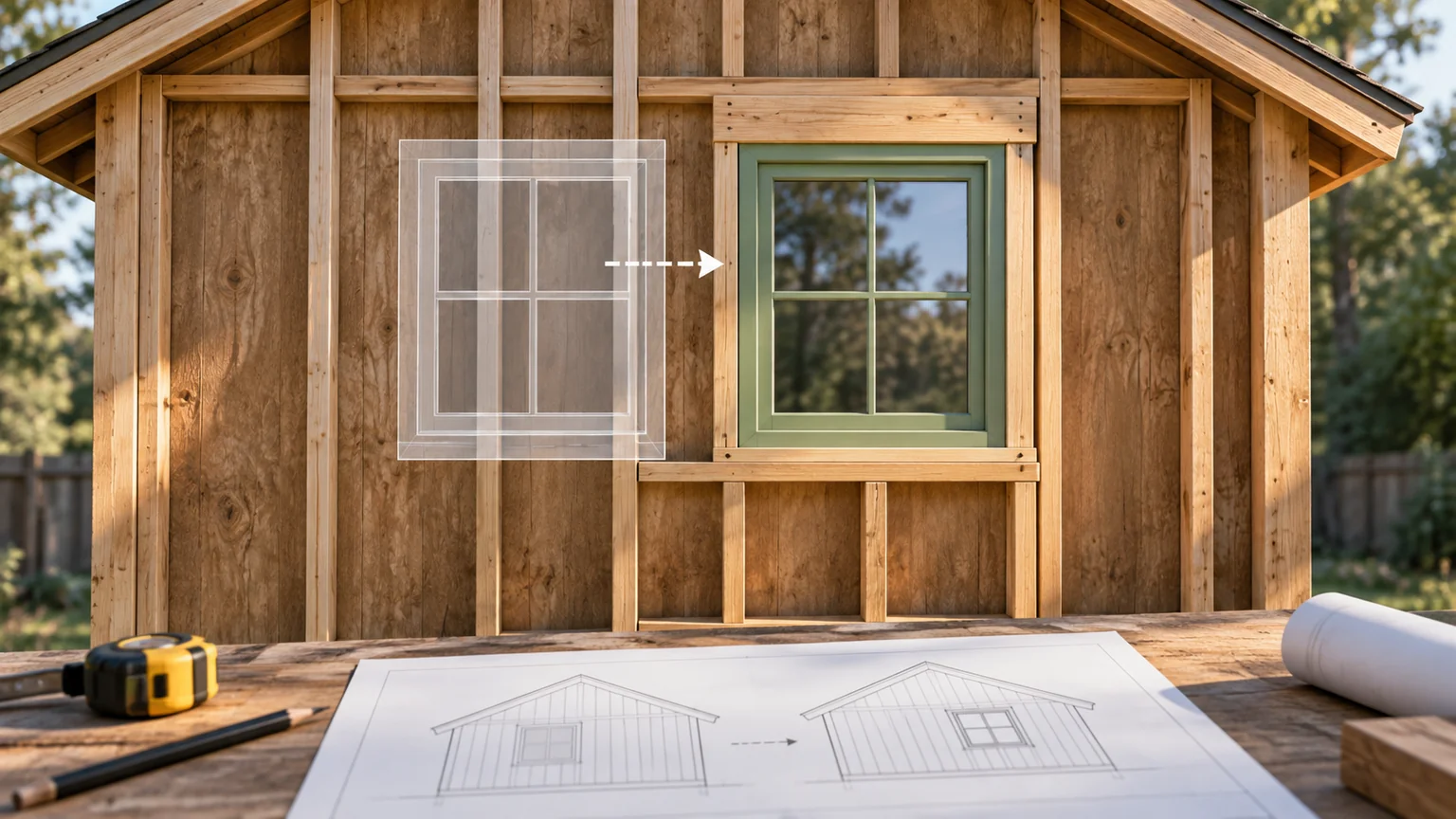
The model’s front opening, D01, is 60 inches wide and 78 inches high. Those are dimensions of the framed hole. The usable passage through a selected door depends on its frame, leaves, hardware and opening position. Do not order a “60-inch door” on the assumption that these dimensions mean the same thing.
Keep a short opening schedule:
| Opening | Modeled location and size | Still to choose |
|---|---|---|
| D01, front door | Centered; 60 × 78 in framed opening; bottom at finished-floor zero | Door product, required rough opening, clear passage and threshold detail |
| W01, rear window | Centered; 36 × 36 in opening; sill 43½ in above finished floor | Window product, required rough opening and installation detail |
Use the product’s own installation instructions to reconcile the opening. In a drawing, finished floor is a reference level: the surface you stand on. Stating that reference avoids an offset being measured from the underside of the floor in one view and the top in another.
Check the garden, driveway and delivery route
The route begins outside the shed. Check the gate, corners, slopes and the place a delivery vehicle or installer could reach. A generous door cannot compensate for an approach the object cannot negotiate.
Make a site sketch with the proposed position, known services, ground levels and where water goes after rain. Take the intended use and location to the relevant local authority; do not treat the footprint as a permission answer. Record which questions need a survey, site investigation or design decision.
The model shows three lengthwise timber skids beneath transverse floor joists. That arrangement is an adopted study detail. It does not determine the foundation, bearing, anchorage or moisture protection appropriate for your ground. Keep those decisions in the same brief as the building dimensions so they are resolved before the work is priced as a complete job.
Understand the roof shape and where rain will go
A 6:12 pitch rises 6 inches for every 12 inches of horizontal travel. Across the example’s 5-foot half-width, that slope produces a 30-inch rise. The ridge follows the 12-foot length.
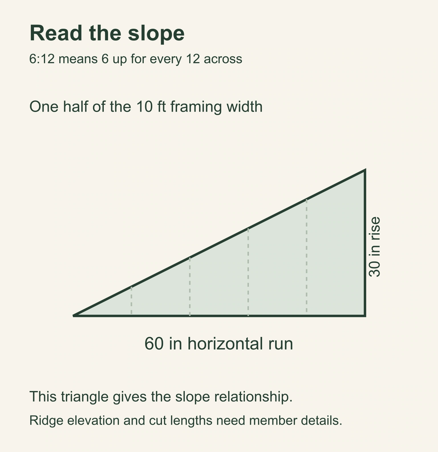
That small triangle explains the slope. It does not give the actual ridge elevation or the length of a cut rafter. The member depth, ridge connection, bearing seat and overhang affect those details. The American Wood Council’s span-table tutorial also distinguishes a rafter’s horizontal design span from its sloping length; member selection needs the relevant loads, supports, species and grade. Read the AWC tutorial.
Now follow rain from each roof face to its intended discharge point. Ask for the junction details at the roof, window, wall base and any attachment. Ask where roof water will discharge and how the selected roof joins the walls and openings. Flashing—the material that directs water away from vulnerable joints—and product installation details need to be coordinated with the site.
Compare quotes for the same work
The model can count its geometric parts. It cannot turn that count into a complete shopping list without decisions about products, connections, stock lengths and cutting allowances. Keep modeled quantities, purchase quantities and allowances separate.
When comparing proposals, give everyone the same brief and ask what is included: site preparation, foundation, shell, doors and windows, weatherproofing, services, delivery and installation. An attractive total is difficult to judge when one proposal includes work that another excludes.
Leave with one useful page
Put these six answers on the first page of your brief:
- Use: what you will store and what you need to do inside.
- Inside dimensions: measured to the finished boundary you intend to use.
- Movement: largest object, clear door passage and a tested route.
- Site: access, water, services and questions still awaiting an answer.
- Building: opening schedule, roof section and the details still to be designed.
- Scope: the work you want included in a proposal, with a date and revision.
Return to the first wet afternoon. Can you reach the bicycle without emptying the shed? Can you work at the bench with the door closed? If the plan answers those everyday questions, you have a much stronger basis for the next design conversation. Use the free area calculator and planning worksheet to keep the arithmetic alongside it. When a proposal arrives, use the five checks for a 3D building plan to compare the drawings, review and price.
Keep a good idea close.
Follow Blueprint Lab